can i draw 3d object in visual studio
This browser is no longer supported.
Upgrade to Microsoft Edge to take advantage of the latest features, security updates, and technical support.
Model editor
This document describes how to piece of work with the Visual Studio Model Editor to view, create, and modify 3D models.
You can utilize Model Editor to create basic 3D models from scratch, or to view and modify more than-complex 3D models that were created by using full-featured 3D modeling tools.
Supported formats
The Model Editor supports several 3D model formats that are used in DirectX app development:
| Format Proper name | File Extension | Supported Operations (View, Edit, Create) |
|---|---|---|
| AutoDesk FBX Interchange File | .fbx | View, Edit, Create |
| Collada DAE File | .dae | View, Edit (Modifications to Collada DAE files are saved past using the FBX format.) |
| OBJ | .obj | View, Edit (Modifications to OBJ files are saved by using the FBX format.) |
Get started
This department describes how to add together a 3D model to your Visual Studio C++ project and other basic information that will help you get started.
Note
Automatic build integration of graphics items similar 3D scenes (.fbx files) is simply supported for C++ projects.
To add together a 3D model to your project
-
Ensure you have the required Visual Studio component installed that you lot need to work with graphics. The component is called Paradigm and 3D model editors.
To install it, open Visual Studio Installer by selecting Tools > Get Tools and Features from the card bar, and so select the Private components tab. Select the Epitome and 3D model editors component under the Games and Graphics category, and then select Alter.
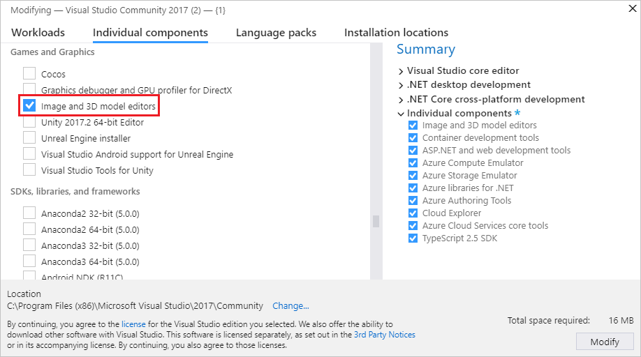
The component starts installing.
-
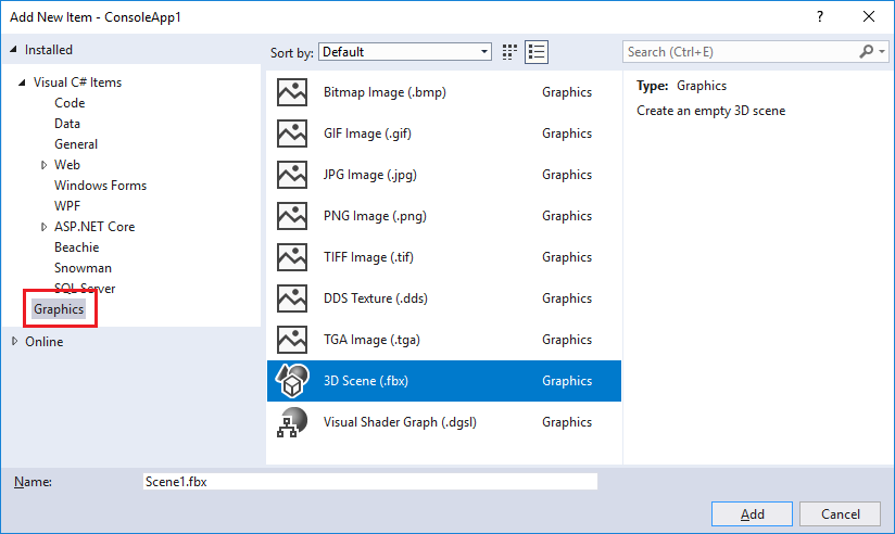
In Solution Explorer, open up the shortcut carte for the C++ project yous want to add the paradigm to, and then choose Add together > New Item.
-
In the Add New Particular dialog box, under the Graphics category, select 3D Scene (.fbx).
Note
If you don't see the Graphics category in the Add together New Item dialog, and you lot accept the Image and 3D model editors component installed, graphics items are not supported for your project type.
-
Enter the Proper name of the model file, so select Add.
Axis orientation
Visual Studio supports every orientation of the 3D axis, and loads axis orientation data from model file formats that back up it. If no axis orientation is specified, Visual Studio uses the right-handed coordinate system by default. The axis indicator shows the current axis orientation in the lower-right corner of the design surface. On the axis indicator, cherry-red represents the ten-axis, green represents the y-axis, and blue represents the z-axis.
Brainstorm your 3D model
In the Model Editor, each new object e'er begins as 1 of the basic 3D shapes—or primitives—that are congenital into the Model Editor. To create new and unique objects y'all add together a primitive to the scene and then change its shape by modifying its vertices. For complex shapes, you add together additional vertices by using extrusion or subdivision and and then change them. For information near how to add a primitive object to your scene, see Create and import 3D objects. For information about how to add together more than vertices to an object, see Alter objects.
Work with the Model Editor
The post-obit sections describe how to utilise the Model Editor to work with 3D models.
Model Editor toolbars
The Model Editor toolbars contain commands that aid y'all piece of work with 3D models.
Commands that bear on the state of the Model Editor are located on the Model Editor Mode toolbar in the main Visual Studio window. Modeling tools and scripted commands are located on the Model Editor toolbar on the Model Editor design surface.
Here'southward the Model Editor Mode toolbar:

This table describes the items on the Model Editor Style toolbar, which are listed in the social club in which they appear from left to right.
| Toolbar Detail | Clarification |
|---|---|
| Select | Enables option of points, edges, faces, or objects in the scene, depending on the agile selection manner. |
| Pan | Enables movement of a 3D scene relative to the window frame. To pan, select a bespeak in the scene and motion it around. In Select way, you lot can printing and concur Ctrl to activate Pan mode temporarily. |
| Zoom | Enables the display of more than or less scene particular relative to the window frame. In Zoom mode, select a betoken in the scene and and so move it right or down to zoom in, or left or up to zoom out. In Select mode, y'all can zoom in or out by using the mouse cycle while you press and hold Ctrl. |
| Orbit | Positions the view on a circular path around the selected object. If no object is selected, the path is centered on the scene origin. Note: This fashion has no event when Orthographic project is enabled. |
| World Local | When this item is enabled, transformations on the selected object occur in globe-infinite. Otherwise, transformations on the selected object occur in local-space. |
| Pivot Mode | When this item is enabled, transformations affect the location and orientation of the pivot point of the selected object (The pin point defines the center of translation, scaling, and rotation operations.) Otherwise, transformations affect the location and orientation of the object's geometry, relative to the pivot point. |
| Lock 10 centrality | Restricts object manipulation to the ten axis. Applies only when you use the centre role of the manipulator widget. |
| Lock Y axis | Restricts object manipulation to the y axis. Applies just when you utilise the centre function of the manipulator widget. |
| Lock Z axis | Restricts object manipulation to the z axis. Applies only when yous use the center role of the manipulator widget. |
| Frame Object | Frames the selected object so that it's located in the eye of the view. |
| View | Sets the view orientation. Here are the available orientations: Front end Dorsum Left Right Summit Lesser |
| Projection | Sets the kind of projection that is used to draw the scene. Here are the bachelor projections: Perspective Orthographic |
| Draw Style | Sets how objects in the scene are rendered. Here are the available styles: Wire Frame Overdraw Apartment Shaded If none of these options are enabled, each object is rendered by using the cloth that'southward practical to information technology. |
| Real-Time Rendering Manner | When real-time rendering is enabled, Visual Studio redraws the design surface, even when no user action is performed. This mode is useful when you work with shaders that alter over time. |
| Toggle Grid | When this item is enabled, a grid is displayed. Otherwise, the filigree is not displayed. |
| Toolbox | Alternately shows or hides the Toolbox. |
| Document Outline | Alternately shows or hides the Document Outline window. |
| Properties | Alternately shows or hides the Properties window. |
| Advanced | Contains advanced commands and options. Graphics Engines Render with D3D11 Render with D3D11WARP Scene Management Import Adhere to Parent Detach from Parent Create Group Merge Objects Create New Object From Polygon Selection Tools Flip Polygon Winding Remove All Animation Triangulate View Backface Culling Frame Rate This selection is useful when you enable the Real-Time Rendering Fashion option. Show All Show Face Normals Testify Missing Materials Testify Pin Show Placeholder Nodes Show Vertex Normals |
Here's the Model Editor toolbar:

The next table describes the items on the Model Editor toolbar, which are listed in the society in which they appear from tiptop to bottom.
| Toolbar Detail | Description |
|---|---|
| Translate | Moves the selection. |
| Scale | Changes the size of the selection. |
| Rotate | Rotates the selection. |
| Select Indicate | Sets the Selection mode to select individual points on an object. |
| Select Border | Sets the Selection mode to select an edge (a line betwixt ii vertices) on an object. |
| Select Face | Sets the Selection mode to select a face on an object. |
| Select Object | Sets the Selection mode to select an entire object. |
| Extrude | Creates an additional face and connects it to the selected face up. |
| Subdivide | Divides each selected face into multiple faces. To create the new faces, new vertices are added—one in the center of the original face, and one in the middle of each border—and and so joined together with the original vertices. The number of added faces is equal to the number of edges in the original face. |
Control the view
The 3D scene is rendered according to the view, which can be idea of equally a virtual camera that has a position and an orientation. To change the position and orientation, utilise the view controls on the Model Editor Mode toolbar.
The post-obit tabular array describes the primary view controls.
| View Command | Description |
|---|---|
| Pan | Enables movement of a 3D scene relative to the window frame. To pan, select a point in the scene and move it around. In Select manner, y'all tin press and hold Ctrl to activate Pan mode temporarily. |
| Zoom | Enables the brandish of more or less scene detail relative to the window frame. In Zoom mode, select a point in the scene and and then move it right or down to zoom in, or left or up to zoom out. In Select mode, you lot can zoom in or out by using the mouse bike while y'all press and hold Ctrl. |
| Orbit | Positions the view on a circular path around the selected object. If no object is selected, the path is centered on the scene origin. Note: This fashion has no result when Orthographic projection is enabled. |
| Frame Object | Frames the selected object so that information technology'due south located in the heart of the view. |
The view is established by the virtual camera, but it's likewise defined by a projection. The project defines how shapes and objects in the view are translated into pixels on the pattern surface. On the Model Editor toolbar, you can choose either Perspective or Orthographic projection.
| Projection | Description |
|---|---|
| Perspective | In perspective projection, objects that are farther away from the viewpoint appear smaller in size and ultimately converge to a point in the distance. |
| Orthographic | In Orthographic projection, objects appear to be the same size, regardless of their distance from the viewpoint. No convergence is displayed. When Orthographic project enabled, you can't employ Orbit manner to position the view arbitrarily. |
You might find it useful to view a 3D scene from a known position and angle, for example, when you want to compare two similar scenes. For this scenario, the Model Editor provides several predefined views. To use a predefined view, on the Model Editor Style toolbar, choose View, and and then cull the predefined view you want—front end, back, left, correct, superlative, or lesser. In these views, the virtual camera looks directly at the origin of the scene. For example, if you choose View Top, the virtual camera looks at the origin of the scene from directly above it.
View additional geometry details
To better understand a 3D object or scene, you can view additional geometry details such equally per-vertex normals, per-confront normals, the pin points of the active option, and other details. To enable or disable them, on the Model Editor toolbar, cull Scripts > View, and then cull the one you want.
Create and import 3D objects
To add a predefined 3D shape to the scene, in the Toolbox, select the one you desire and and so move it to the pattern surface. New shapes are positioned at the origin of the scene. The Model Editor provides seven shapes: Cone, Cube, Cylinder, Disc, Plane, Sphere, and Teapot.
To import a 3D object from a file, on the Model Editor toolbar, choose Advanced > Scene Management > Import > and then specify the file that y'all want to import.
Transform objects
You can transform an object by changing its Rotation, Calibration, and Translation properties. Rotation orients an object by applying successive rotations around the x-axis, y-axis, and z-axis defined by its pin bespeak. Each rotation specification has iii components—ten, y, and z, in that order—and the components are specified in degrees. Scaling resizes an object by stretching it by a specified factor along one or more axes centered on its pivot point. Translation locates an object in three-dimensional infinite relative to its parent instead of its pivot point.
Y'all can transform and object either by using modeling tools or by setting properties.
Transform an object past using modeling tools
-
In Select mode, select the object y'all want to transform. A wireframe overlay indicates that the object is selected.
-
On the Model Editor toolbar, choose the Translate, Scale, or Rotate tool. A translation, scaling, or rotation manipulator appears for the selected object.
-
Employ the manipulator to perform the transformation. For translation and scaling transformations, the manipulator is an centrality indicator. You can change one axis at a time, or y'all can change all axes at the same time past using the white cube at the center of the indicator. For rotation, the manipulator is a sphere fabricated of colour-coded circles that represent to the x-axis (reddish), y-axis (green), and z-axis (blue). Yous have to change each axis individually to create the rotation you want.
Transform an object by setting its properties
-
In Select way, select the object that you desire to transform. A wireframe overlay indicates that the object is selected.
-
In the Properties window, specify values for the Rotation, Scale, and Translation backdrop.
Important
For the Rotation property, specify the caste of rotation around each of the iii axes. Rotations are applied in social club, and then brand sure to plan a rotation, offset in terms of the x-centrality rotation, then the y-axis, and and then the z-axis.
Past using the modeling tools, you can create transformations chop-chop but not precisely. By setting the object properties, you tin can specify transformations precisely just not quickly. We recommend that you use the modeling tools to get "close enough" to the transformations you want, and and then fine-tune the belongings values.
If you don't want to apply manipulators, you tin enable free-form fashion. On the Model Editor toolbar, choose Scripts > Tools > Complimentary-form Manipulation to enable (or disable) free-class manner. In gratis-form way, you can begin a manipulation at whatsoever point on the pattern surface instead of a indicate on the manipulator. In gratis-form way, y'all tin can constrain changes to certain axes by locking the ones you don't desire to modify. On the Model Editor Mode toolbar, choose any combination of the Lock X, Lock Y, and Lock Z buttons.
Y'all might find it useful to work with objects by using snap-to-grid. On the Model Editor Style toolbar, choose Snap to enable (or disable) snap-to-grid. When snap-to-grid is enabled, translation, rotation, and scaling transformations are constrained to predefined increments.
Work with the pivot point
The pivot point of an object defines its middle of rotation and scaling. You can change the pivot point of an object to modify how it's affected by rotation and scaling transformations. On the Model Editor Mode toolbar, choose Pin Style to enable (or disabled) pivot mode. When pivot manner is enabled, a small axis indicator appears at the pivot point of the selected object. You tin can and then employ the Translation and Rotation tools to manipulate the pivot point.
For a demonstration that shows how to use the pivot point, see How to: Modify the pivot point of a 3D model.
World and local modes
Translation and rotation can occur in either the local coordinate system (or local frame-of-reference) of the object, or in the coordinate system of the globe (or the globe frame-of-reference). The world frame-of-reference is independent of the rotation of the object. Local way is the default. To enable (or disable) earth way, on the Model Editor Mode toolbar, choose the WorldLocal push.
Change objects
Y'all can modify the shape of a 3D object by moving or deleting its vertices, edges, and faces. Past default, the Model Editor is in object mode, so that you can select and transform unabridged objects. To select points, edges, or faces, choose the appropriate choice mode. On the Model Editor Mode toolbar, choose Selection modes, and so cull the style that you want.
You tin can create boosted vertices past extrusion or by subdivision. Extrusion duplicates the vertices of a face (a co-planar ready of vertices), which remain continued past the duplicated vertices. Subdivision adds vertices to create several faces where there was previously one. To create the new faces, new vertices are added—one in the center of the original face, and one in the centre of each edge—and and then joined together with the original vertices. The number of added faces is equal to the number of edges in the original face. In both cases, you can interpret, rotate, and scale the new vertices to alter the geometry of the object.
To extrude a face from an object
-
In face-select manner, select the face yous want to extrude.
-
On the Model Editor toolbar, cull Scripts > Tools > Extrude.
To subdivide faces
-
In face-select style, select the faces you want to subdivide. Because subdivision creates new edge information, subdividing all faces at in one case gives more-consistent results when the faces are adjacent.
-
On the Model Editor toolbar, choose Scripts > Tools > Subdivide.
You can also triangulate faces, merge objects, and convert polygon selections into new objects. Triangulation creates additional edges such that a non-triangular face up is converted to an optimal number of triangles; nonetheless, information technology doesn't provide additional geometric detail. Merging combines selected objects into 1 object. New objects can be created from a polygon choice.
Triangulate a face
-
In face-select style, select the face you desire to triangulate.
-
On the Model Editor toolbar, cull Scripts > Tools > Triangulate.
Merge objects
-
In object-select manner, select the objects you desire to merge.
-
On the Model Editor toolbar, choose Scripts > Tools > Merge Objects.
Create an object from a polygon selection
-
In face-select manner, select the faces you want to create a new object from.
-
On the Model Editor toolbar, choose Scripts > Tools > Create New Object from Polygon Selection.
Work with materials and shaders
The advent of an object is determined by the interaction of lighting in the scene and the fabric of the object. Materials are defined past backdrop that depict how the surface reacts to unlike types of low-cal and by a shader plan that calculates the terminal color of each pixel on the object surface based on lighting information, texture maps, normal maps, and other data.
The Model Editor provides these default materials:
| Material | Description |
|---|---|
| Unlit | Renders a surface without any simulated lighting. |
| Lambert | Renders a surface with simulated ambient lighting and diffuse lighting. |
| Phong | Renders a surface with simulated ambient lighting, diffuse lighting, and specular highlights. |
Each of these materials applies i texture on the surface of an object. You can prepare a different texture for each object that uses the fabric.
To modify how a item object reacts to the unlike light sources in the scene, you tin change the lighting backdrop of textile independent of other objects that use the material. This table describes mutual lighting backdrop:
| Lighting Holding | Clarification |
|---|---|
| Ambient | Describes how the surface is affected past ambient lighting. |
| Diffuse | Describes how the surface is affected by directional and point lights. |
| Emissive | Describes how the surface emits low-cal, contained of other lighting. |
| Specular | Describes how the surface reflects directional and point lights. |
| Specular Power | Describes the breadth and intensity of specular highlights. |
Depending on what a material supports, you tin change its lighting properties, textures, and other data. In Select way, select the object whose fabric y'all want to alter, and so in the Properties window, modify the MaterialAmbient, MaterialDiffuse, MaterialEmissive, MaterialSpecular, MaterialSpecularPower, or other available belongings. A material can expose up to eight textures, whose properties are named sequentially from Texture1 to Texture8.
To remove all materials from an object, on the Model Editor toolbar, choose Scripts > Materials > Remove Materials.
You lot tin utilize the Shader Designer to create custom shader materials that you can utilise to objects in your 3D scene. For information nigh how to create custom shader materials, run into Shader Designer. For information about how to apply a custom shader material to an object, see How to: Apply a shader to a 3D model.
Scene management
Y'all tin manage scenes as a hierarchy of objects. When multiple objects are arranged in a hierarchy, whatever translation, scale, or rotation of a parent node too affects its children. This is useful when yous want to construct complex objects or scenes from more than basic objects.
Yous can employ the Document Outline window to view the scene hierarchy and select scene nodes. When you select a node in the outline, you tin use the Properties window to change its properties.
You can construct a hierarchy of objects either by making one of them the parent to the others or by grouping them together as siblings under a placeholder node that acts every bit the parent.
Create a hierarchy that has a parent object
-
In Select mode, select two or more objects. The first i you select volition exist the parent object.
-
On the Model Editor toolbar, choose Scripts > Scene Management > Attach to Parent.
Create a hierarchy of sibling objects
-
In Select mode, select two or more objects. A placeholder object is created and becomes their parent object.
-
On the Model Editor toolbar, choose Scripts > Scene Management > Create Group.
The Model Editor uses a white wireframe to identify the start selected object, which becomes the parent. Other objects in the option have a blue wireframe. By default, placeholder nodes are non displayed. To brandish placeholder nodes, on the Model Editor toolbar, choose Scripts > Scene Management > Show Placeholder Nodes. You can work with placeholder nodes only as you piece of work with non-placeholder objects.
To remove the parent-kid clan between two objects, select the child object, and then on the Model Editor toolbar, choose Scripts > Scene Management > Detach from Parent. When you detach the parent from a kid object, the child object becomes a root object in the scene.
Keyboard shortcuts
| Command | Keyboard shortcuts |
|---|---|
| Switch to Select style | Ctrl+1000, Ctrl+Q South |
| Switch to Zoom style | Ctrl+G, Ctrl+Z Z |
| Switch to Pan mode | Ctrl+K, Ctrl+P K |
| Select all | Ctrl+A |
| Delete the electric current option | Delete |
| Cancel the current selection | Escape (Esc) |
| Zoom in | Mouse wheel frontwards Ctrl+Mouse cycle forwards Shift+Mouse wheel forrard Ctrl+PageUp Plus Sign (+) |
| Zoom out | Mouse wheel backward Ctrl+Mouse wheel backward Shift+Mouse wheel backward Ctrl+PageDown Minus Sign (-) |
| Pan the photographic camera upward | PageDown |
| Pan the camera down | PageUp |
| Pan the photographic camera left | Mouse cycle left Ctrl+PageDown |
| Pan the camera right | Mouse bike correct Ctrl+PageDown |
| View top of model | Ctrl+50, Ctrl+T T |
| View bottom of model | Ctrl+L, Ctrl+U |
| View left side of model | Ctrl+50, Ctrl+Fifty |
| View right side of model | Ctrl+50, Ctrl+R |
| View front of model | Ctrl+50, Ctrl+F |
| View back of model | Ctrl+L, Ctrl+B |
| Frame object in window | F |
| Toggle wireframe fashion | Ctrl+50, Ctrl+W |
| Toggle snap-to-grid | Ctrl+M, Ctrl+Due north |
| Toggle pin mode | Ctrl+G, Ctrl+V |
| Toggle x-axis restriction | Ctrl+L, Ctrl+10 |
| Toggle y-axis restriction | Ctrl+50, Ctrl+Y |
| Toggle z-axis restriction | Ctrl+L, Ctrl+Z |
| Switch to translation mode | Ctrl+G, Ctrl+W W |
| Switch to scale mode | Ctrl+1000, Ctrl+E Eastward |
| Switch to rotation manner | Ctrl+1000, Ctrl+R R |
| Switch to point-select mode | Ctrl+L, Ctrl+1 |
| Switch to border-select fashion | Ctrl+50, Ctrl+2 |
| Switch to face-select mode | Ctrl+L, Ctrl+3 |
| Switch to object-select manner | Ctrl+L, Ctrl+4 |
| Switch to orbit (camera) mode | Ctrl+Grand, Ctrl+O |
| Select next object in scene | Tab |
| Select previous object in scene | Shift+Tab |
| Dispense the selected object based on the current tool. | The Pointer keys |
| Conciliate current manipulator | Q |
| Rotate camera | Alt+Elevate with left mouse button |
| Championship | Description |
|---|---|
| Working with 3D assets for games and apps | Provides an overview of the Visual Studio tools that y'all tin apply to work with graphics assets such as textures and images, 3D models, and shader effects. |
| Image Editor | Describes how to utilise the Visual Studio Image Editor to piece of work with textures and images. |
| Shader Designer | Describes how to use the Visual Studio Shader Designer to work with shaders. |
Feedback
Submit and view feedback for
Source: https://docs.microsoft.com/en-us/visualstudio/designers/model-editor
0 Response to "can i draw 3d object in visual studio"
Enregistrer un commentaire